Pogo Pin Characteristics
Common structure of pogo pin
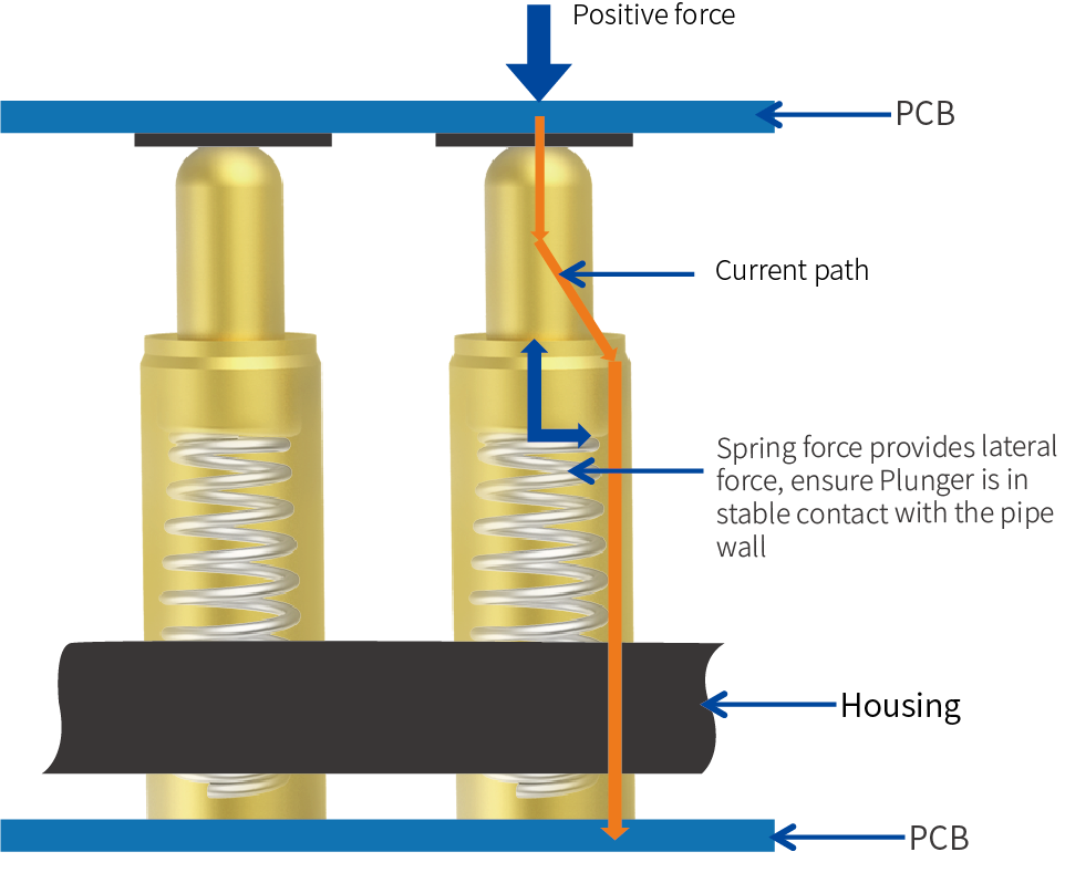
Pogo pin contact principle
Characteristics
- Long service time, 10,000 times
- No tooling fee,easy go customize
- Adjustable and measurable spring force
- Fine pitch
- Flexible manufacturing ways: SMT,plug-in...
- Save space: help mechanical engineer easily allocatecomponents on PCB
- Good performance on RF solution
- RoHS and Halogen Free
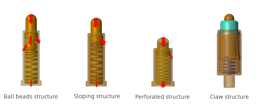
Common internal structure of Pogo Pin

| Structure | Ball beads structure | Sloping structure | Perforated structure | Claw structure |
|---|
| Contact impedance | ≤ 10mΩ | ≤ 30mΩ | ≤ 50mΩ | ≤ 5mΩ |
| Long service time | 10000+ | 10000+ | 10000+ | 500+ |
| Recommended working current | 10A max | 10A max | 10A max | 10A max |
| Contact stability | ★ ★ ★ ★ ☆ | ★ ★ ★ ☆ ☆ | ★ ★ ★ ☆ ☆ | ★ ★ ★ ★ ★ |
| Processing cost | ★ ★ ★ ☆ ☆ | ★ ★ ☆ ☆ ☆ | ★ ★ ☆ ☆ ☆ | ★ ★ ★ ★ ☆ |
| Main application areas | Mainly used for charging and condition with certain requirements for vibration and shock | Mainly used for charging or signal transmission of Consumer electronics | Mainly used for signal transmission or grounding antenna,etc. | Mainly used high-frequency,anti-instantaneous,the situation which high-reliability is required,such as base stations,military industries,vehicles. |
| Remarks | The beads increase the internal contacts,the contact is more stable,and the more needle space is required | The most commonly used structure on the market | The space is smaller,but the contact is not stable,the current is easy to run through the spring,and it is not recommended for charging | The needle and the needle tube have multiple contacts to increase the contact stability |
Product Model
| Index | | L | W | H | Pitch | Cap | Positioner | A | B | C | D | Working height | Froce(gf) | PDF |
|---|
| Index | | L | W | H | Pitch | Cap | Positioner | A | B | C | D | Working height | Froce(gf) | PDF |
|---|
| 1 | 110806-7 | 17.78 | 2.54 | 2.4 | 2.54 | N | N | 2 | 0.4 | 2.8 | 3.8 | 3.2 | 60 Min | |
| 2 | 110491-7 | 17.78 | 2.54 | 2.4 | 2.54 | N | N | 2 | 1 | 5 | 7 | 6 | 80 Min | |
| 3 | 10101071201 | 17.84 | 2.5 | 2 | 2.54 | Y | N | 1.8 | 0.5 | 3.3 | 4.5 | 3.5 | 90±20 | |
| Index | | L | W | H | Pitch | Cap | Positioner | A | B | C | D | E | F | Working height | Froce(gf) | PDF |
|---|
| Index | | L | W | H | Pitch | Cap | Positioner | A | B | C | D | E | F | Working height | Froce(gf) | PDF |
|---|
| 1 | 110951-7 | 17.78 | 2.54 | 2.4 | 2.54 | N | N | 1 | 1 | 2 | 0.5 | 3.5 | 5 | 3.8 | 120±30 | |
| 2 | 110187-7 | 18.54 | 5.3.7 | 13.5 | 2.54 | N | Y | 1 | 3.6 | 1.83 | 0.4 | 16.57 | 18.07 | 17.07 | 90+30/-15 | |