
Precision Connectivity
for Humanoid Robots
From joint actuators and dexterous hands to auto-docking charge and battery-swap interfaces — a dual technology route of Claw-Spring contacts × Pogo Pin covers power, signal and high-speed interconnect across the entire robot body.
* Figures are based on the specifications and test conditions of the corresponding products; final values are subject to official datasheets. 224 Gbps is an R&D achievement of Micro Pogo for AI-server / chip-test scenarios; dedicated robot models are not yet finalized.
Why Humanoid Robots Push Connectivity to the Limit
Walking, turning, lifting, bending, grabbing — robot joints endure constant vibration, shock, posture changes and space constraints. Internal connections must deliver power and signals while staying compact, vibration-tolerant and maintainable.
Continuous Dynamic Motion
Joints and fingers are high-frequency, multi-axis, small-amplitude mechanisms. Vibration-induced contact interruption and micro-wear cause encoder frame loss and distorted force feedback — contacts must remain stable in motion.
Extremely Constrained Space
A single dexterous-hand finger cavity may be only a few millimeters, yet must house actuation, sensing and signal transmission. Connectors must be miniature and high-density while tolerating assembly tolerances and thermal deformation.
Modular Design & Maintenance
Replaceable joints, fingers and battery modules demand plug-in interfaces: electrical connection completes on insertion — no per-wire soldering or crimping — shortening downtime during maintenance.
Claw-Spring × Pogo Pin — One System, Two Contact Families

Claw-Spring Contacts
Elastic spring blades form multi-point, circumferential contact with the mating terminal — large contact area, high current-carrying potential and inherent tolerance to vibration and shock.
Best suited for:

Pogo Pin / Micro Pogo
Pin shaft, spring and barrel form a three-segment axial elastic contact — conduct on compression, release to separate, and naturally suited to dense arrays.
Best suited for:
Three Charging Architectures, Not One
Charging interfaces should not be treated as one structure. By docking method there are three architectures — auto-dock charging, quick-plug charging and battery-swap modules — each with its own safety logic and mechanics. What they share is one system logic:
Mechanical interface locates and locks first — contacts never carry mechanical load
Detect presence, polarity and identity
Main power closes only after safety conditions are met (pre-charge / soft-start when required)
Monitor temperature and contact state throughout the process
Disconnect power and confirm residual energy is discharged before withdrawal

Auto-Dock Charging
Vision / positioning / mechanical guidance aligns the robot to the dock. High-current contacts + independent detection/communication contacts + guide structure; Pogo Pin spring travel absorbs centimeter-level alignment error. Watch for lateral/angular offset, effective compression, temperature rise, dust and oxidation.
Quick-Plug Charging
Manual or automatic quick-plug, or flush-surface docking, optionally with a locking structure. Anti-reverse, anti-loosening and anti-mistouch are mandatory; if hot-plugging is unavoidable, evaluate pilot contacts, pre-charge / current limiting or disconnect-first strategies — never assume a standard Pogo Pin tolerates live mating.
Battery-Swap Module
The swap interface carries the battery main circuit — higher voltage, current and short-circuit energy. A scaled-up charging Pogo Pin is not enough: use proven dedicated power contacts for the main circuit; multi-pin elastic contacts for auxiliary power, BMS communication, identification and temperature; plus pre-charge, interlock and polarity protection.
Magnetic attraction only assists alignment — mechanical positioning, shear resistance and anti-mistouch must still be carried by structural parts. Magnets alone are not a locking solution.
Ten Application Locations, One Connectivity Map
Joint Servo Actuators
Low-voltage supply, feedback and control signals between actuator, encoder and sensor boards — contact stability must be verified under vibration.
Modular Joint Connections
Push-in joints connect power, control, identification and diagnostics. Keys: blind-mate guidance, position tolerance, insertion force, locking and maintenance life.
Dexterous-Hand Finger Modules
High-density arrays between finger modules and palm control board: Micro Pogo combines low-voltage supply, control signals, tactile data and module identification.
Tactile & Torque Sensing
Sensor supply and low-level/analog signals. Contact-resistance drift, noise, grounding and shielding directly affect measurement accuracy.
Board-to-Board Stacking
Stacked or flush-mated main / driver / function boards: power, ground, control and differential data channels — contact layout and PCB routing co-designed.
Head Vision & Perception
Compact board-to-board interfaces for detachable sensing modules: power, configuration, synchronization and differential data channels.
Battery & Low-Voltage Power
Multi-channel interconnect between pack, BMS and distribution board; the main circuit uses safety-verified power connections.
End-Effector Quick Change
Gripper/tool quick-change interface: power, control, identification and sensing. The mechanical coupler carries torque shock — contacts never act as the lock.
High-Speed Differential Links
Short-reach high-speed channels between main control and vision/perception: differential impedance, insertion loss, return loss and crosstalk verified on the complete channel.
Production Test & Calibration
Fixtures flash, test and calibrate PCBA, joints and sensor modules: temporary contact, test-point access, signal injection — cycle time and durability matter.
Key Locations, Examined One by One
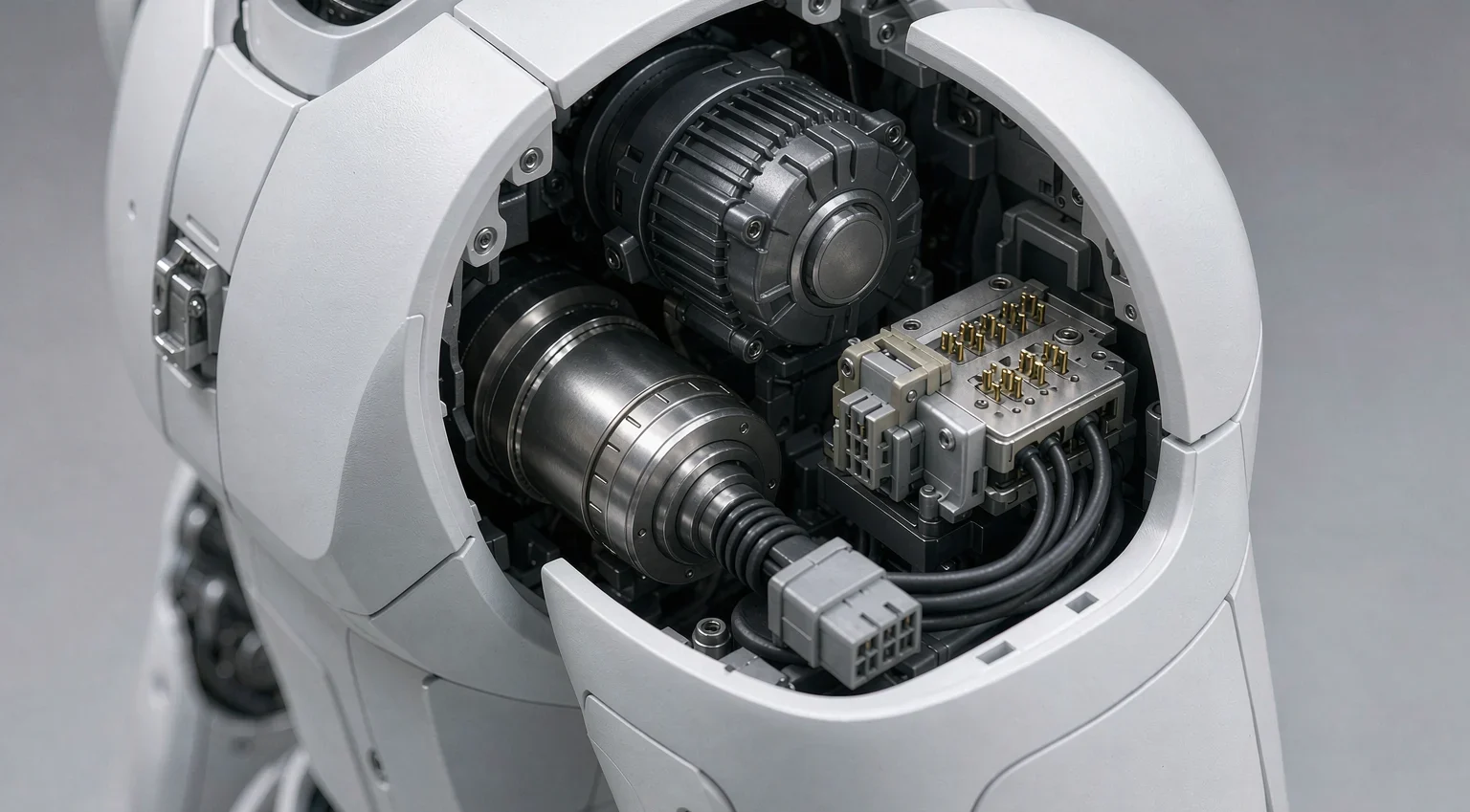
Shoulder / Elbow / Hip / Knee Actuators
Periodic vibration, shock and temperature swings. Removable power terminals for joint modules; verify separately at peak and continuous current, including start, stall and braking. For large-angle continuous rotation, switch to flexible harnesses or slip rings.
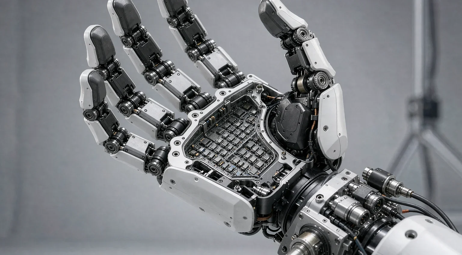
Wrist & Dexterous Hand
The wrist is where hand-assembly power and signals converge. Partition power contacts from low-level signal contacts; add mechanical guidance, keying and locking; make palm and finger-root modules detachable with strain relief and controlled bend radius.
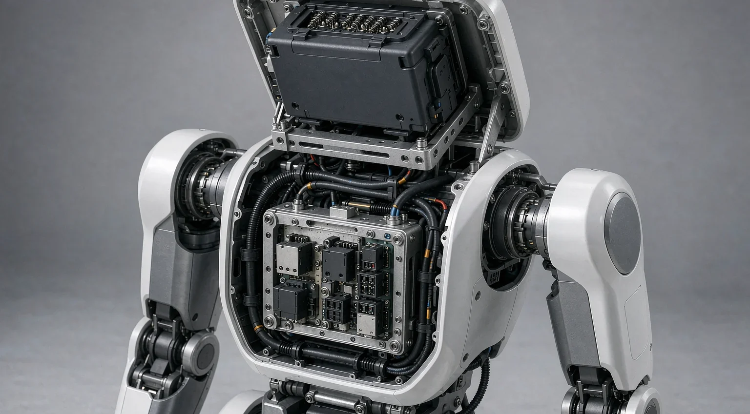
Torso: Battery & Power Distribution
Battery, distribution and main controller concentrate in the torso. Select plug-in power connections by current and voltage class; the battery main circuit involves high energy — add pilot contacts, interlocks or control strategy so mating only happens after power-off or verified safety.
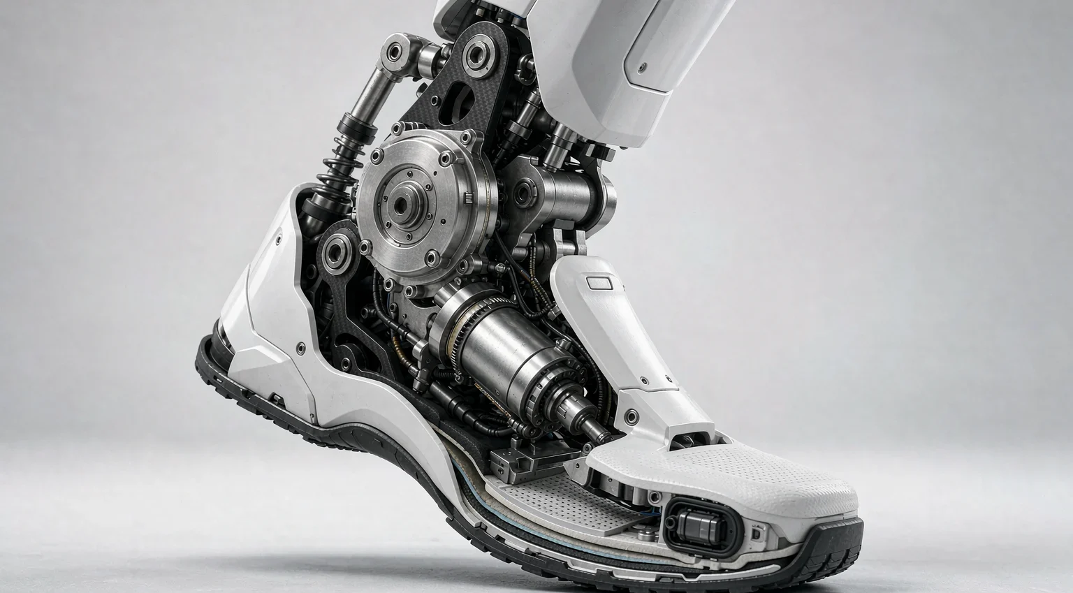
Ankle & Foot
Walking, stair climbing and landing shock. Mechanical positioning and housing protection come first — contacts carry no impact load. Test dynamic contact resistance and noise for force/pressure sensors and IMUs; select plating, sealing and cleaning by the whole-machine IP rating.
Typical Application Schemes
Quick-Swappable Dexterous Hand
Wrist-end module interface with guidance and locking; claw-spring contacts carry hand power or higher-current supply, other contacts carry communication and sensing. Power off or confirm safety through interlock before swapping.
Maintainable Actuator Module
Design the driver or motor module as a detachable unit; claw-spring contacts connect the specified power circuit. Housing and screws carry fixation and shock loads — contacts do electrical work only.
Palm-Level Replaceable Fingers
Anti-mistouch keying plus modular interface at the finger root; claw-spring on suitable power channels, signal channels selected separately by bandwidth and noise requirements. Harnesses get fixed anchor points and strain relief.
Battery / Power Module Maintenance
Evaluate claw-spring contact schemes for removable low-voltage power modules with mechanical anti-error, short-circuit protection and mating-state detection. High-voltage or high-energy circuits require a complete connector system meeting the applicable safety standard.
Verify Against Real Conditions, Not Datasheet Numbers
Humanoid robots face repeated motion, shock, vibration, temperature swings and complex environments. Selection must be based on real usage conditions — never on static rated current or pin counts alone. We recommend building a DVP&R (Design Verification Plan & Report) at the product-definition stage.
Mechanical
Insertion cycles, mating force, compression travel, lateral misalignment, vibration / shock — does contact stay stable after life testing? Do modules stay locked?
Electrical
Contact resistance, insulation resistance, withstand voltage (where applicable), current-induced temperature rise — safe at rated and abnormal conditions?
Environmental
High/low temperature, temperature cycling, humidity, corrosion / contamination (chosen per the real environment) — do surfaces and contacts degrade?
High-Speed Signals
Differential impedance, insertion/return loss and crosstalk measured on the complete channel; BER and eye closure verified under vibration for robot-relevant links.
Frequently Asked Questions
Which robot locations suit claw-spring contacts, and which suit Pogo Pin?
Actuator power terminals, replaceable hand/finger modules and removable power components — anywhere needing higher current and vibration tolerance — favor claw-spring. Charging docks, blind-mate docking and compact control-board interfaces — anywhere needing axial compensation and dense arrays — favor Pogo Pin. Both can be combined within one module by signal type.
Isn't a magnetic charging dock already a reliable connection?
No. Magnets only assist attraction and alignment; mechanical positioning, shear resistance and anti-mistouch must be carried by structural parts. The correct sequence: locate & lock → contact → confirm polarity, state and safety → then allow charging current.
Can Pogo Pins be used in the robot battery main circuit?
The main circuit involves higher voltage, current and short-circuit energy — never scale up a charging Pogo Pin for it. Layer the design: proven dedicated power contacts for the main path; Pogo Pins for auxiliary power, BMS communication, identification and temperature signals; pre-charge, interlock and polarity protection mandatory.
Can 224 Gbps / 90 GHz high-speed figures be applied to robots directly?
No. These capabilities come from Micro Pogo R&D for AI-server / chip-test scenarios; dedicated robot models are not yet finalized. Before real use, confirm operating temperature and vibration class for servo environments, and measure contact-resistance fluctuation and BER under vibration. Metrics must not be extrapolated across product families.
How do you connect continuously rotating joints like shoulders?
Standard claw-spring and Pogo Pin interconnects are not continuous-rotation solutions. For large-angle or continuous rotation, evaluate flexible harnesses, controlled-torsion harnesses or slip rings; plug-in contacts are for detachable module interfaces, not for conduction during motion.
How do we start selection and sampling?
Six steps: (1) map connection functions (main/auxiliary power, ground, communication, sensing, charging); (2) define electrical needs (rated/peak current, voltage, temperature rise, bandwidth); (3) define mechanical conditions (static/periodic/rotating, space, travel, tolerance); (4) choose the architecture combination; (5) verify temperature rise, dynamic conduction, vibration, life and environment on samples; (6) refine materials, plating and structure, then finalize.
Get Your Humanoid Robot Connectivity Solution
Share your application locations, current, signal types, installation space and operating conditions — our engineers will match a claw-spring / Pogo Pin custom scheme and arrange sample verification.
Contact Our Engineering Team